controller
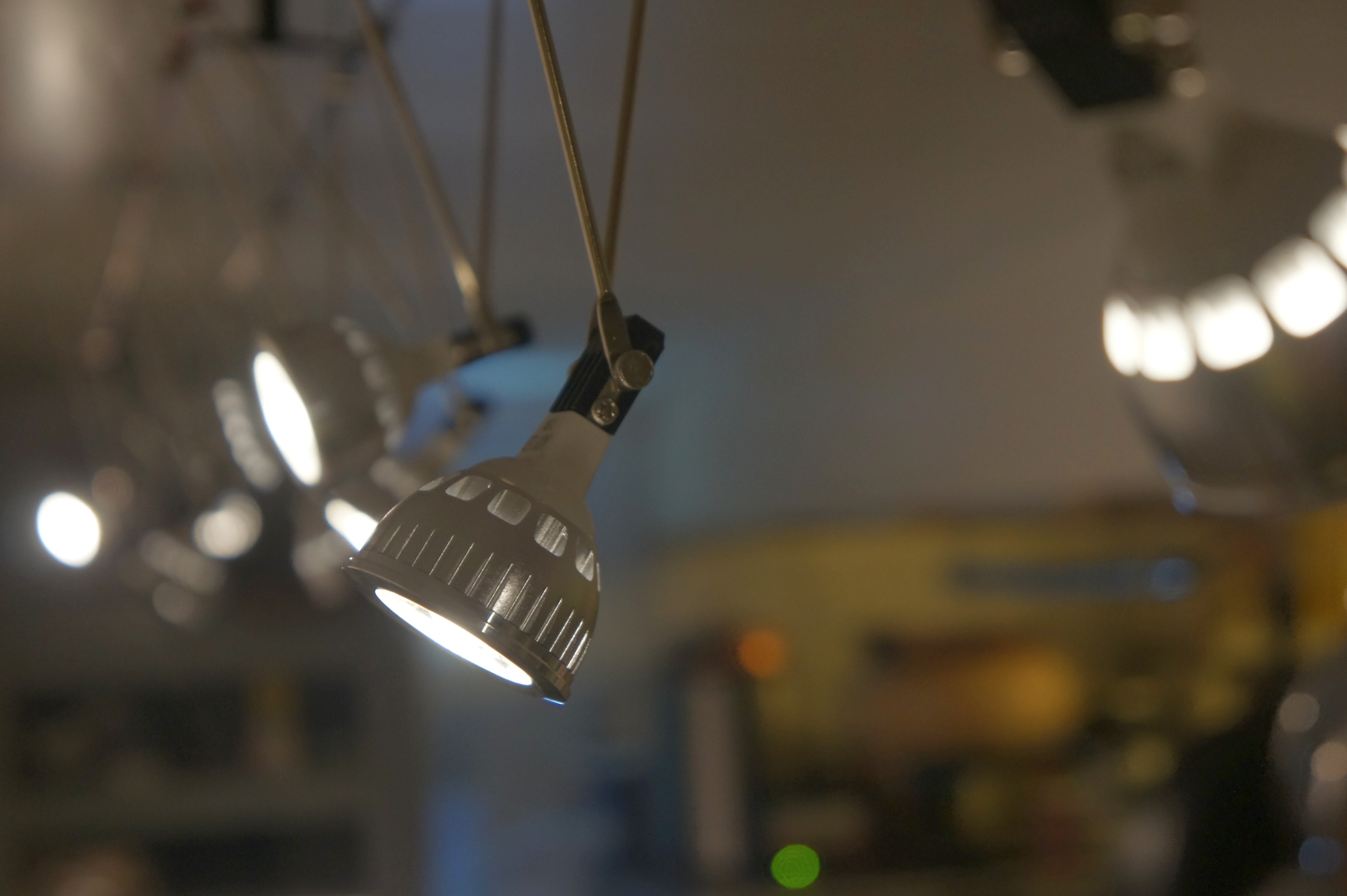
Low Voltage LED Lighting
My kitchen has had halogen lighting for 20 years, from back when it was a slightly more efficient choice than incandescent lighting and had a pleasing, cooler (bluer, meaning the filament runs hotter) color temperature.
Progress has moved on and while fluorescent lights still have a lead in maximum luminous efficacy (lm/w), for example the GE Ecolux Watt-Miser puts out 111 lm/W, they’re less versatile than LEDs and installation is a hassle while low voltage LEDs are easy to install and look cool.
System Design
The goal of this project was to add dimmable, pleasing light to the kitchen that I found aesthetically interesting. I wanted a decent color rendering index (CRI), ease of installation, and at reasonable cost. I’ve always liked the look of cable lighting and the flexibility of the individual, adjustable luminaires.
I couldn’t find much information on how variable output LEDs work and what can be used to drive them. I have a pretty good collection of high quality power supplies, which I wanted to take advantage of, but wasn’t sure if I’d be able to effectively dim the bulbs from the documentation I found. So I did some tests.
Test Configuration
I bought a few different 12V, Dimmable LEDs and set up a test configuration to verify operation and output with variable voltage and variable current. The one bit of data I had was that using standard commercial controllers, the lowest output is typically stated to be around 70% of maximum output: that is the dimming range is pretty limited with standard (PWM/Transformer) controllers. The results I found were much more encouraging, but revealed some quirks.
I used a laboratory-grade HP power supply with voltage and current control to drive the LEDs, decent multimeters to measure voltage and current, and an inexpensive luminance meter to measure LED output.
I measured 3 different LEDs I selected based on price and expected compatibility with the aesthetics of the project and because they looked like they’d have different internal drivers and covered a range of rated wattage.
Test Results
These bulbs have internal LED controllers that do some sort of current regulation for the diodes that results in a weird voltage/current/output response. Each bulb has a different turn-on voltage, then responds fairly predictably to increasing input voltage with increasing output, reaches the controller stabilizing voltage and runs very inefficiently until voltage gets over the rated voltage and then becomes increasingly efficient until, presumably, at some point the controller burns out. I find that the bulbs all run more efficiently at 14V than at the rated 12V.
As a side note, to perform the data analysis, I used the excellent xongrid plugin for excel to perform Kriging interpolation (AKA Gaussian process regression) to fit the data sets to the graphing function’s capabilities. The graphs are generated with M-Chart and the table with TablePress.
Watts v. Volts
This chart shows the wattage consumed by each of the three LEDs as a function of input voltage, clearly demonstrating both that the power consumption function is non-linear and that power consumption in watts improves when driven over the rated 12V. Watts are calculated as the product of the measured Volts * Amps. Because of the current inversion that happens as the controllers come fully on-line, these LEDs can’t be properly controlled near full brightness with a current-controlled power supply, though it works well to provide continuous and fairly linear dimming at low outputs, once the voltage/current function changes slope, the current limiting controller in the power supply freaks out.
Lux v. Volts
This chart shows the lux output by each of the three LEDs as a function of input voltage, revealing the effect of the internal LED driver coming on line and regulating output, which complicates controlling brightness but protects the LEDs. The 5W LEDs have a fairly gentle response slope and start a very low voltage (2V) so are a good choice for a linear power supply. The 4W LEDs don’t begin to light up until just over 6V, and so are a good match for low-cost switch mode supplies that don’t go to zero.
Lux/W v. Volts
This chart shows the luminous efficiency (Lux/Watt, Lumen measurement is quite complicated) by each of the three LEDs as a function of input voltage, showing that overdriving the LEDs past the rated 12V can significantly improve efficiency. There’s some risk it will overheat the controller at some point and result in failure. I’ll update this post if my system starts to fry LEDs, but my guess is that 14V, which cuts the power load by 20% over 12V operation with the 7.5W lamps I selected, will not significantly impact operational lifetime.
Update: This system has been running for 7 years now. In that time two linear power supplies have failed (they were fairly inexpensive models as such things go). The LED modules had a high infant mortality rate: 2-3 failed in the first few months, another one failed just about every 6 months for the first couple of years. I think it has been 4 years since the last one failed. This implies that longevity is primarily a function of build quality, which varies.
Total System Efficiency
The emitter efficiency is relatively objective, but the total system efficiency includes the power supply. I used a Daiwa SS-330W switching power supply I happened to have in stock to drive the system, which cost less than a dimmable transformer and matching controller, and should be significantly higher quality. The Daiwa doesn’t seem to be easily available any more, but something like this would work well for up to 5A total load and something like this would handle as many as 40 7.5W LEDs on a single control, though the minimum 9V output has to be matched to LEDs to get satisfactory dimming. It is important not to oversize the power supply too much as switch mode supplies are only really efficient as you get close to their rated output. An oversized switchmode power supply can be extremely inefficient.
With the Daiwa, driving 13 7.5W LEDs, I measured 8.46A at 11.94V output or 101 Watts to brightly illuminate the entire kitchen, and providing far more light than 400W of total halogen lights. I measured the input into the power supply at 0.940A at 121.3V or 114 Watts. That means the power supply is 88.6% efficient at 12V, which is more or less as expected for a variable output supply.
Increasing the output voltage to 14.63 Volts lowered the output current to 5.35A or 78 Watts without lowering the brightness at the installation; I measured at 168 lux at both 12.0V at 14.6V. The input current at 14.63V dropped to 0.755A or 91.6 Watts, meaning the power supply is slightly less efficient at lower output currents (as is usually the case).
- Overdriving the 12V rated LEDs to 14.63V improves plug efficiency by 20%.
At the low end, the SS-330W’s minimum output is 4.88V, which yields 12 lux at the counter or a 14x dimming ratio to 7% of maximum illumination, a far better range than is reported for standard dimmer/transformer combinations.
Parts
- 7.5W LED modules from JackyLED
- Daiwa power supply (alternate version)
- 16 gauge speaker cable
- MR-16 cable lamp mounts
- Digital light meter
Raw Data:
(MS Excel file, you will need the xongrid plugin to update the data as rendered in the graphs)
Updating an IBM 335
I’m bringing up an old IBM 335 for use as a pfSense Firewall. It is a fine computer, with almost everything you’d want except dual power supplies (the 336 has those plus 64 bit hardware).
![]()
The first step is updating the machine:
- BIOS to 1.16: download the flash image, it writes itself to a floppy, boot with that floppy and flash the BIOS. I had to go through a bunch of 1990’s era software disks until I found a few floppies that would format without errors. This also updates the LSI 1030 disk controller.
- Internal Diagnostics to 1.07: these are disk images (.img) diskcopy didn’t seem to do the right thing on my XP box, so I used diskwriter 0.9 to create the disks. You boot off the BIOS update disk then select update diagnostics.
- Configure the disks with ServeRAID. I didn’t flash the BIOS on the controller, but I did reformat the disks and set them up as RAID 1.
- Update the System Management Processor to 1.06. This is a self-booting floppy.
- Update the Broadcom NetXtreme NICs to 209h. This is a self-booting floppy that creates a RAM disk then runs the update. The command for the 335 is
UPDATE 8830
This gets the core hardware up to date. You might also want to flash the firmware in the disks, though I did not as my box is loaded with unsupported disks. Plus 36GB SCSI disks aren’t exactly going through a lot of teething pains these days.
Then I installed pfSense from the LiveCD (verify the hash). This is pretty effortless. The only important bit of data is to set up the NICs: in the 335 under FreeBSD bge0 is the lower port and bge1 is the upper port.
At a later date I will install a 73P9265 Remote Supervisor II adapater, but the cable I have (73P9312) is for newer boxes. The 335 needs the 02R1661: oddly it is cheaper to buy the cable with a card than just the cable. This will probably need flashing of the firmware, but is a nice tool with remote KVM and a lot of other slick features.
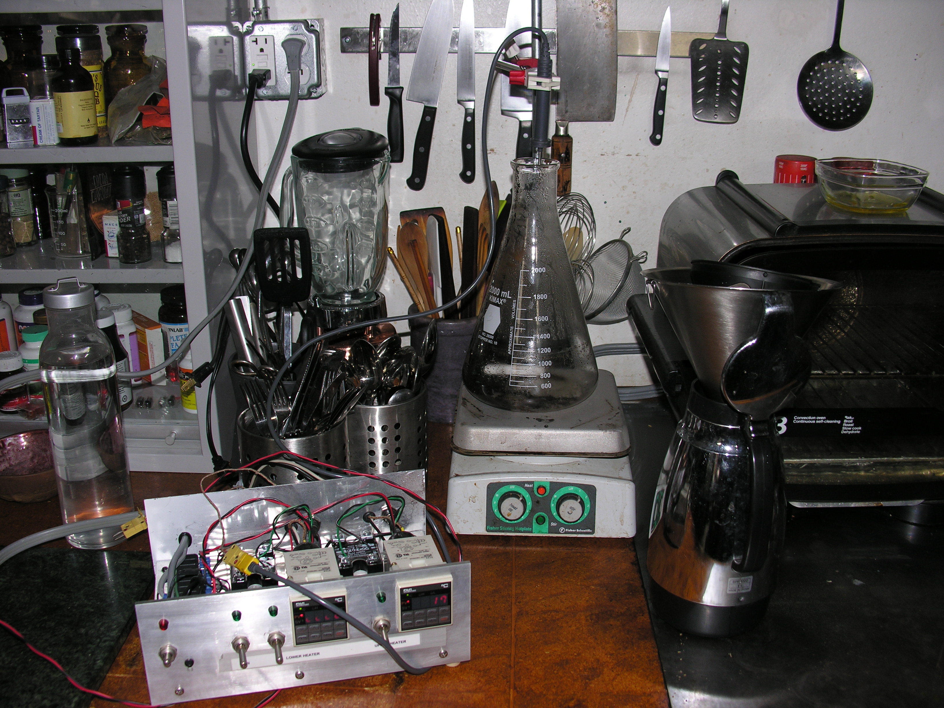
Coffee Science Update
Magnetically stirred coffee seems to be a success, but still tuning the parameters. I have a surplus temperature control module connected to a thermocouple probe to monitor the temperature.
My first attempt was confounded by not programming the controller to read a K-type thermocouple, it came set for a J-type and so the water never got over 88C even boiling… which it did for a while and that’s not good. Not good at all.
Today I let the water temp get up to 80C and the coffee was very good, smooth and not bitter at all. Perhaps a bit too smooth, a bit like the cold-brew taste but warm and much faster thanks to the stirring action. I will try 90C tomorrow and if success continues, modify the hotplate to add a direct thermal element bypass to the outside so the temp controller can control the heater directly (now I just watch and turn off the heater at the target temp.)
The theory is that by continuously stirring the coffee, a lot of flavor is extracted without relying on heat, and that the stirring also ensures uniform heating through the entire volume and thus the temperature can be set fairly precisely (to about a degree C, +/- 1 degree or so) to optimize differential extraction of the organics in the grounds.
Racking fun
fans

The rack system we use to house our servers….
The house is not air conditioned and the rack is effectively in the garage, so it needs both dust filtering and self-adjusting cooling to compensate for summer daytimes without being insanely noisy all the time. The fans have taken a little trial and error to get configured right. They are connected to this industrial controller that turns on fans sequentially as the temperature rises.
I just got the door fans repaired after a minor accident that sent one blade flying, and came to two observations:
- The fans are loud.
- I’m not optimally supporting the designed cooling system for the servers.
I visited a massive colo facility a while back and they went on about using CFD to calculate the flow rates through their cages to keep 20kw racks from melting down (about 15 space heaters inside a box) and one thing they mentioned was sealing all the gaps between the front and back of the rack. Clearly I have not done this. The bit I didn’t really think of is that the rack isn’t so much a chimney filled with rising hot air as a jet with the intake at the front and the exhaust at the back. The fan system needs to enhance that jet flow, not some chimney effect with hot air exiting out the top.
That said, normally racks are put in environments where dust isn’t a problem. So I need positive pressure fans to pressurize the front of the rack through filters and compensate for the pressure drop through the media. That should provide plenty of clean, ambient temp air for the server fans to blow through the rack (and provide enough air that the server fans don’t create negative pressure in the front and draw dirty air in though other openings in the front half of the rack).
If that positive pressure turns out to be inadequate, then the temperature controller will turn on negative pressure fans at the back of the rack to exhaust the heated air, which will necessarily increase the flow through the servers and presumably drop the pressure in the front of the rack below ambient and thus, worst case, draw in a mix of dirty and clean air. The compromise is that a bit of dust is better than overheating on hot days.
The temp controller is currently set to turn on supplemental cooling at 85F (inside the rack temp). Since ambient hits 85 on the worst days, that seems like the lowest reasonable temperature to set the controller to.
In the end, if that’s not enough, then a ton of chilled water should do the trick, but I’m hoping not to have to go there…